Topics
Graphical terminology for machine description
2020-06-19
A safe and effective use of machines requires an understanding of their design and function. This description, which is not yet a direct instruction, requires a lot of effort in creation, maintenance and translation. In order to minimize this effort, a graphic terminology has been developed that allows the structure and function of the machine to be presented essentially language-independently.
Initial situation
- Operating instructions in mechanical and plant engineering
- maximum cost pressure, because special machines
- Presentation of the special machine manufacturers:
“… our customer knows what is delivered …”,
“… that is everything agreed upon…”,
“…you can see everything on the machine…”
Basis for the requirement for a machine description
- EU Machinery Directive
“… general description of the machine”. - ISO 12100-1
“detailed description of the machine …” - IEC 82079
“The operating instructions must contain applicable information relating to the product itself: detailed description of the product, its accessories, …”.
Classical machine description
Example for a short description of the swivel rotary table of a machine tool
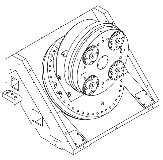
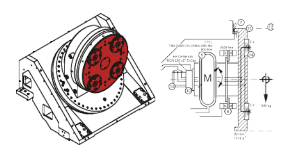
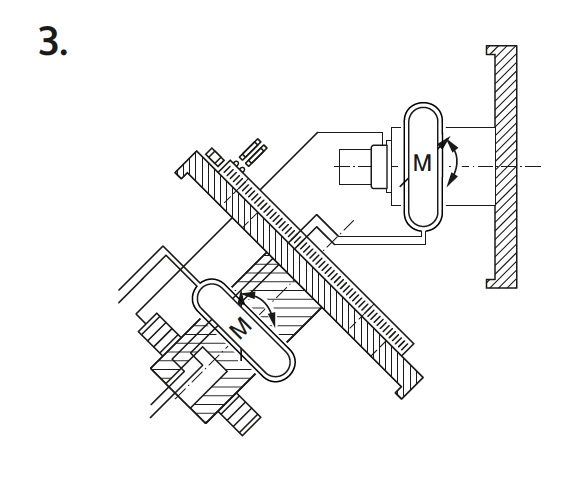
Swivel rotary table
A simple example:
“The swivel rotary table has a swivel axis A and a rotation axis C. Both axes are driven and positioned by a water-cooled built-in motor. The swivel angle of the swivel axis A is monitored by a scanning head, the end positions by two inductive sensors. The angle of rotation of the rotary axis C is monitored by an angle measuring device. Both axes are held in position by a spring force clamp. The spring force clamping is released hydraulically. The housings of both axes are protected against contamination by sealing air on the face plate. On the face plate of the rotary axis C there are four spring-loaded clamping elements for holding a machine pallet. The clamping elements are released hydraulically. A hydraulic rotary lead-through is located in the C axis of rotation to supply the clamping elements. All media are transferred to the entire machine via an energy chain on the A-axis”.
This fraction of an operating manual, with 928 characters and approx. 17 lines, could correspond to 170 € at a line price of 1 € and 10 languages.
Advantages
- proven, common and accepted
- simple and can be created by any author
Disadvantages
- expensive to maintain (even the smallest changes require a translation run)
no reading motivation - Interrelationships cannot be quickly understood
Graphic machine description
The graphic machine description is the basis of technical communication. This type of machine description is extensively standardized:
- Machine construction drawings
- Fluid diagrams
- E-plans
- Lubrication schedules
- Software (program flow chart, structure chart)
- Description of processes
- Functional diagrams
- Manufacturer-dependent schemes
Advantages
- high understanding rate in the main areas
- extensively standardized
Disadvantages
- mostly media related
- mostly not suitable for describing relationships across media, assemblies and functions
- Connections are often only made by special number ranges with different identification letters and formats
Graphical terminology for machine description
Based on the above-mentioned example of a classic machine description, the swivel rotary table will be described graphically below.
A simple example
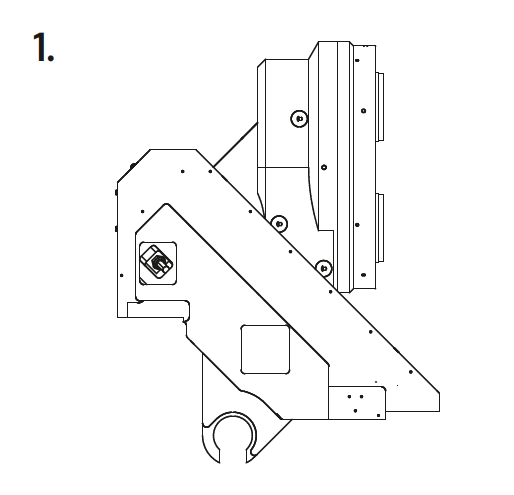
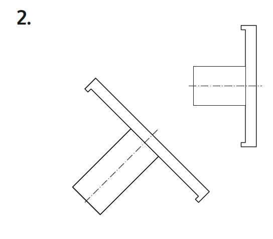
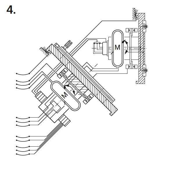
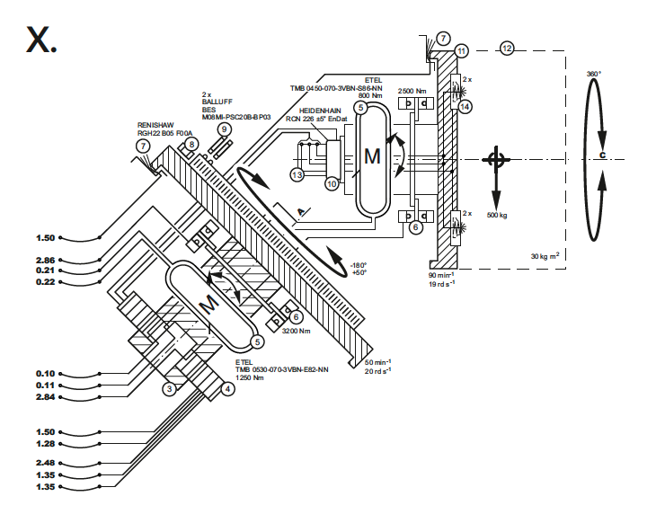
Graphic description of the swivel turntable
A more complex example:
Graphical description of a special transporter, based on:
- 2 pages format-A0 pneumatic plans
- 10 pages format-A0 hydraulic plans
- 100 pages format A4 E-plans
- 2 pages format-A1 Cold scheme
- 2 pages format-A1 Exhaust system
- 3 pages format-A1 fuel system
Graphical description of a special transporter
Advantages
- cross-media
- Interrelationships and comprehensive functions can be described
- Interrelationships can be understood very quickly
- high reading motivation
- Replacement for a classic machine description
- low translation costs
- target group-oriented
Disadvantages
- not standardized in this form
- only standardized in partial areas
- a legend for description is necessary (but much less text, due to simple grammar and nouns, a translation run is rarely necessary when changes are made)
- user tests are necessary
Future outlook
- Further systematization across different industries
- Further systematization across different media, for example data streams and states of modules on a CAN bus
- Use of colors for specific applications
- Internationalization
- Improved user test