Nobody needs much explanation about what "Zack", "Zisch" or "Peng" stands for. Reading a comic is enough. But there is more to a comic than pure entertainment, such as an…
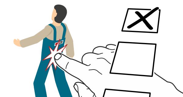
ISO 7010 provides some safety signs. However, depending on the application, these are often either too general, too specific or not available for the specific case. In order to warn…
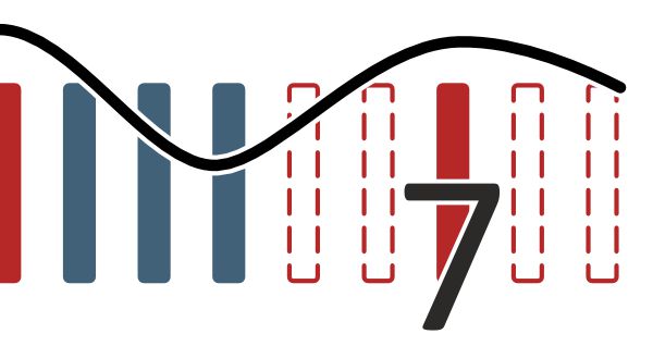
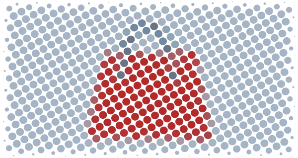
In technical communication, Miller's number plays a crucial role in conveying information effectively. This concept, introduced by George A. Miller in the 1950s, states that human information processing is limited…
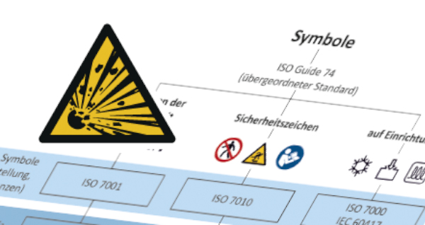
ISO 7010 defines rescue, prohibition, mandatory, warning and fire safety signs and was published in 2012. The safety signs are based on the design criteria of the ISO 3864 series…
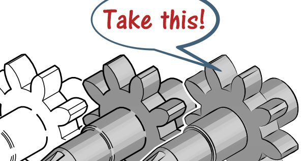
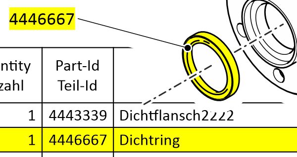
Interactive spare parts catalogs are state of the art: Your customers can easily find and select the parts they need and start the ordering process. This webinar will show you…
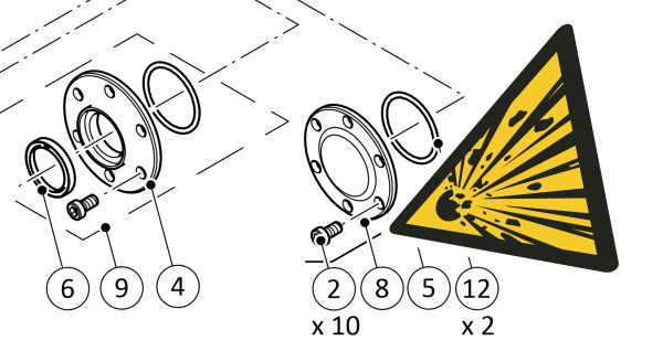
As if pulled up on an imaginary shear, exploded views provide an insight into the inside of devices, machines and systems. They illustrate relationships clearly and help everyone to find,…
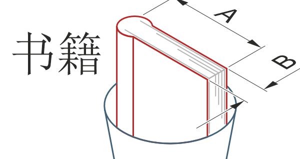
Sometimes it pays to think outside the box, in this case, outside the rice bowl. What we see there is a style guide for technical documents in Chinese and for…