Topics
Technical illustration based on 3D CAD data
2020-09-20
Published as article together with Otto Salzer in technische kommunikation (2020-10), journal of the Gesellschaft für Technische Kommunikation – tekom Deutschland e.V.
Artikel “Die Vorteile richtig ausschöpfen” (pdf) (unfortunately only available in German)
To illustrate a technical documentation, data from a CAD system is suitable. Two-dimensional objects are then created from three-dimensional objects. How can the data transfer be successful? Here are ten answers to ten typical questions.
3D data from CAD applications are often used for technical illustrations. Why is this so? Let’s take a look back: One of the main arguments of software manufacturers so far has been to be able to use 3D data throughout the company by reusing 3D models. If 3D models are only generated in order to derive technical drawings from them, the economic benefit is minimal or even non-existent.
In the meantime, the world looks different – fortunately, which is also thanks to new 3D applications. They are tailored to the requirements of the individual company departments and can therefore economically use the 3D models from the design department in other areas. These include 3D authoring tools, for example. It is therefore all the more surprising that many technical editors still avoid using their own 3D models tailored to their needs. To solve this knot, this article answers ten typical questions.
How do 3D CAD data get into the technical documentation?
Basically, there are three ways of transferring 3D CAD data into the documentation: as bitmap file, as vector file and as 3D PDF.
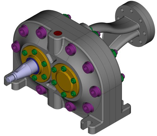
The transfer as a bitmap can be done very easily as a screenshot in the CAD application. In doing so, one does not always take the trouble to adjust the CAD colors of the objects, so that a harlequin-colored machine can be shown in the technical documentation. The user must mentally match it with reality. The case is different with visually high-quality rendered views, prepared in the CAD application itself or in a 3D authoring tool. In either case, the result is a bitmap. The picture shows the effort and experience of the 3D operator.
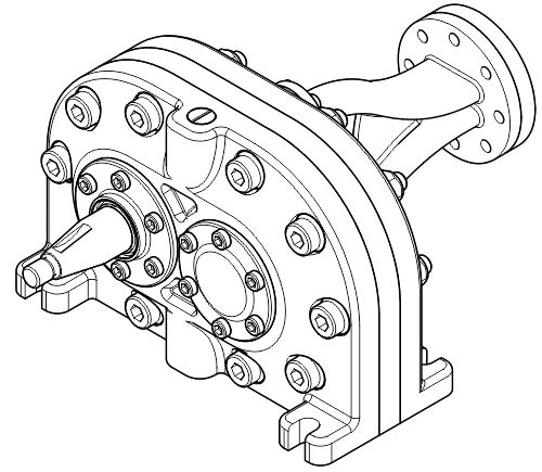
The transfer as vectors can be done again directly from the CAD application. The desired view is then exported into a 2D format (DXF, DWG, SVG) after a hidden line process or just printed into a PDF. The result can then be used to create a technical illustration in a 2D tool.
The 3D-PDF is certainly the best known method for the transfer as 3D model. However, despite great euphoria, the 3D PDF has not become widely accepted. The possibility of publishing 3D data in HTML5 documents via WebGL is gaining in importance. Here you will certainly see more applications in the coming years. On the other hand, the integration of 3D data via proprietary viewers will tend to decrease, as these have a number of disadvantages. For completeness it should be mentioned that complete applications can be published, for example in the area of training through serious game applications or apps.
What is a 3D authoring tool and how does it work?
A 3D authoring tool is a software to prepare existing 3D CAD data for various communication purposes. This can be the creation of standardized views, the representation of assembly steps or the complete explosion for spare parts representations and animations. All this is done in 3D space, but typically not with the original CAD data. Common examples of this authoring tool are SolidWorks Composer, PTC Creo Illustrate and Lattice XVL Studio.
In a typical workflow, the 3D data is first imported from the CAD system. This can be done via standardized exchange formats such as STEP or via the native CAD files. If technical illustrations are the target, views are created in the 3D model in a second step. These contain at least the view angle (camera position), the projection method (parallel or central) and the visibility of the objects (shown or hidden). Furthermore, the positions of the objects in space (assembly, explosion, installation steps), image size, colors (materials), sections or even labels can be defined. In the third step the views are converted into 2D graphics. Here the user has the choice of generating raster or vector graphics. With some 2D formats, such as SVG, it is also possible to output mixed graphics – vector and raster.
Now a specific 2D graphics application such as CorelDRAW, Corel DESIGNER or Adobe Illustrator can be used for further processing.
Does the illustrator need a 3D authoring tool?
Compared to an original CAD application, a 3D authoring tool offers the technical illustrator specific functions at significantly lower license costs and shorter training periods. With a 3D authoring tool, the illustrator can work independently of the source of the CAD data, but still has extensive access to the three-dimensional content.
If it is not planned to work with the 3D CAD data, it is also possible to work with direct exports from the original CAD application. The exports are vectors or bitmaps. If an illustrator does not have an original CAD license, he has to coordinate the data with the design or development department in a time-consuming and possibly nerve-racking manner and request support.
Obviously, a missing authoring tool and the resulting time-consuming procurement of 2D data are the reason for screenshots taken in simple CAD viewers.
Can the process from 3D model to 2D image be fully automated?
Automation is possible for spare parts catalogs, since a defined view, corresponding parts lists and the 3D model provide all the essential information needed to create the base of a catalog. For instructive illustrations or, in general, illustrations with a high communication requirement, it is hardly possible to automate the process from 3D to 2D. Magnifying glasses, cut-outs, didactic enlargements, highlighting, cleaning and additions cannot be generated in the necessary form by an automated process. Such work requires manual skills, product knowledge and the knowledge of the communicative task – three characteristics that can be used to describe the requirements of a technical illustrator well.
”For instructive illustrations or generally spoken illustrations with a high communication requirement it is hardly possible to automate the way from 3D to 2D.
Marco Jänicke
What points should you pay attention to in the illustration?
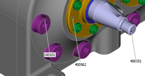
On the one hand we have the problem of too little information. This is caused by components that are not modeled in 3D data, for example media lines, supplier parts or even ambient machine elements. A solution for this can be the insertion of missing 3D objects in the 3D authoring tool. Such objects can be found, for example, at www.traceparts.com. Traceparts is a freely accessible collection of 3D models provided by the manufacturers. For the missing media lines, Lattice in the XVL Studio, for example, offers a solution with the option “Electrical Routing”, which allows cables to be laid and used as in reality. However, the user must license this option separately. Of course, missing objects can also be added in the 2D tool. Even very large differences in object sizes, for example between fasteners and the assembly itself, seem to make details disappear. As a result, very small objects, such as screws, are only displayed as a merged object of lines. The method of choice here is a didactic magnification: only individual objects are magnified to improve their recognizability.
On the other hand, there is the problem that too much information is available. For example, edges can be displayed on freeform surfaces, radius or on composite components. They are not necessary for technical illustration and can even make it difficult to understand.
By configuring the hidden line process, the displayed edges can be influenced. The process can be complex and depends on the model, but can be used again and again for new derivations from 3D to 2D. Alternatively, the objects that are not necessary can be deleted in the 2D tool. This is quick and easy, but must be repeated for new derivations.
What communication aspects should you pay attention to?
Thanks to 3D, you can view objects from angles that remain hidden in reality. Or you can virtually enter machines and systems, zoom in on the smallest details, hide and show parts and assemblies – to name just a few special aspects.
In the CAD world, the designer uses these capabilities, in the 3D authoring tool it is the technical illustrator. And if the 3D data are finally to be part of the user information, the target group itself moves through the three-dimensional virtual scene.
With all the possibilities, it is important to take the viewer with you so that he or she can maintain orientation and assign information. This requirement can be met by indicating the viewing direction in an overview, showing the source in the case of sections and enlargements, clarifying a magnification based on the scale or even showing a reference object that the viewer knows. This additional information should always be based on a typical viewing direction of the customer.
In which format should CAD data be transferred?
The native CAD data contains all information generated by the CAD system. However, this does not mean that all this information is actually transferred via an interface. For example, constraints (constraints between parts) or animations are typically not transferred to another 3D system. Nevertheless, it makes sense to read in the proprietary CAD data, as this is the only way to ensure that only one translation process is necessary.
It should be noted that the proprietary data set of a product usually consists of many files: upper assembly files, subassembly files and parts files. If only a single assembly file is available, referenced objects cannot be displayed. Some CAD systems store a visual representation (simplified polygon representation) of the entire assembly in this file. However, this data does not have the quality of the original data.
In contrast, neutral exchange formats like STEP or IGES are monolithic files. This means that the entire assembly is stored in only one single file. With the JT format, the transfer can take place both in a monolithic and in distributed files.
If neutral data formats are used, two translation processes are always necessary: the first when writing from the CAD system and the second when reading into the 3D authoring tool. Each translation process can reduce the quality of the data. However, JT is currently used as the standard format for visualization, so this data is already available in the PLM system and can be accessed directly.
Which way to go should be decided with test runs. Smaller data sets are send via the different paths from the CAD system to the authoring tool. The quality of the data is then checked in the authoring tool and subsequent applications. The minimum requirements for the data should be that the geometries are transferred cleanly, the assembly structure is kept intact and all metadata can be found on their objects.
What happens when the CAD model is modified?
If a 3D authoring tool was used, the prepared 3D model must first be updated. This usually works very well, since most of the overlapping information (name, ID, metadata) is still present in this process. Additional work can be necessary if new parts are added or existing parts change their dimensions significantly. Then, for example, repositioning is necessary in an exploded view. Then the 2D illustration must be updated in the 2D tool and in the publication. Some tools automate these steps. For example, changes are recognized in Lattice XVL Studio (3D authoring tool) and passed on to Corel DESIGNER (2D illustration). If the DESIGNER files are managed in an editorial system such as DOCUFY COSIMA, gds docuglobe/XR or pgx bloXedia (XML editorial systems), changes are also available here in new publications without any further intermediate steps.
In which step should you create callouts?
Callouts are the link between text and illustration that is most visible to the user. Since the technical writers have a diverse landscape of tools, the creation of callouts is at least as diverse. Let’s take a look at scenarios for this. In the 3D authoring tool, callouts can be placed in 3D space. From a graphical point of view, these objects do not come close to the quality of callouts from a 2D application. Nevertheless, they offer some advantages. Since parts and assemblies are objects in 3D, even a callout recognizes which object it belongs to and can thus automatically receive the desired object information as text. This prevents typing and transmission errors.
In the 2D tool, the Technical Illustrator has the full range of 2D functions. It is advisable to handle the functions systematically, especially if they are supported by the 2D tool. Corel DESIGNER is an example of this. The application has its own labeling object (Callout) with centrally controlled properties. The callout is linked to the objects. In addition, automatic numbering, automatic readout of object data and use as callout text and automatic creation of CGM hotspots are possible. If free text is to be used on the callouts, it can be part of the language translation using an XLIFF file. The translation can then be automatically assigned to the callouts. The callout editors of editorial systems are particularly good at handling text in this way because they are directly integrated into the translation process. In the content management system, the editors place callouts as SVG directly above the image. In this way, identical illustrations can be used with different callouts. Ideally, stylesheets control the display.
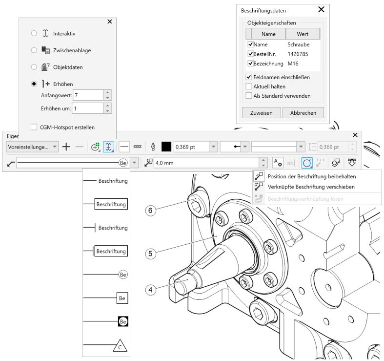
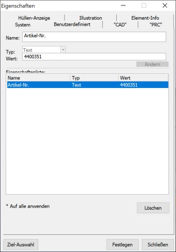
Corel DESIGNER: Control elements around callouts and object data
Lattice XVL Studio:
Check, adjust or create metadata of objects
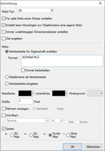
Lattice XVL Studio:
Set up callouts, for example the display and that metadata is automatically used as callout text
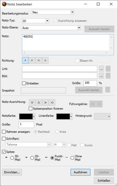
Lattice XVL Studio:
Create callouts, applying the settings for display and metadata
How to manage 3D data in technical documentation?
Once you start working with 3D authoring systems for technical documentation, the technical illustrator has another place to generate information. It is therefore essential to manage this 3D data. The 3D data is used to generate images and illustrations, which are usually further processed in two dimensions. If the 3D source is lost, most of the advantages of CAD are lost, such as rapid adjustments and updates. It would be ideal to have a database-based administration that guarantees a link between the 3D data set and the 2D objects created from it. Typical is the docking to company-wide solutions for document and product data management.
”If the 3D source is lost, most of the advantages of CAD are lost.
Otto Salzer